30 Nov SAMS Project
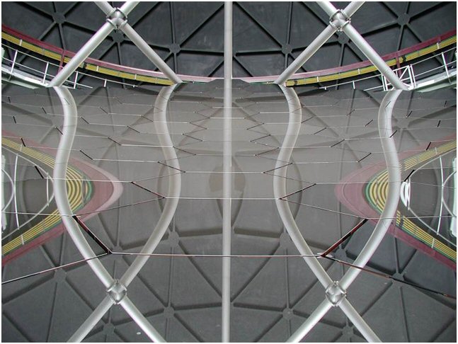
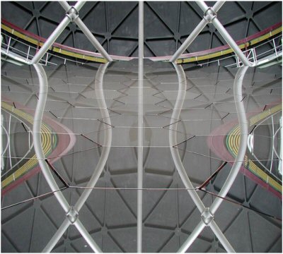
Figure 1. SALT Primary Mirror segments reflecting the interior surface of the dome and structure
What does SAMS mean?
SAMS is an acronym for the SALT Array Management System. It comprises a set of sensors mounted on the mirror segments connected to racks of electronics feeding data to a Labview program that is designed to maintain the overall shape of the SALT mirror array once it has been set up with the CCAS instrument. In its original manifestation, SAMS was used to describe both the hardware setup and the software control program. Currently, we tend to refer to the whole system or to just the hardware as SAMS, but the software, which has been completely rewritten by Deon Bester, is usually called MARS (Mirror Alignment and Reference System).
Why is it needed?
The SALT mirror comprises 91 hexagonal segments figured to have spherical surfaces with a radius of curvature of 26.165 m. When all segments are pointing to a common focus, they act as a 10-m spherical mirror.
There are 3 actuators attached to each segment that provide the ability to change its pointing direction. The 91 mirror segment mounts are supported on a steel truss that expands and contracts as the temperature increases or decreases, carrying the segments with it. The CCAS instrument is used to align the mirror segments by adjusting the actuators so that the segments all point to a common focus. As the truss contracts it is necessary to adjust the actuators to compensate and to maintain the correct focus. It is the job of the edge sensors mounted on the backs of the segments to provide the information needed to make the correct adjustments. They do this by constantly comparing the positions of adjacent edges and supplying the relative heights to a Labview program that computes how the actuators should be moved.
Edge sensors?
When SALT was commissioned in 2006 it had sensors bonded to opposing flat edges of the segments that acted as capacitors in an electrical circuit. As the segments moved, the capacitance changed, providing a measure of both the separation of the edges (the ‘Gap’) and their relative heights (the ‘Piston’). The Gap measure is directly related to the temperature experienced by the truss. Unfortunately, capacitors are sensitive to relative humidity – and although Sutherland is in the Karoo desert, there is typically an increase of humidity during a night of up to 60%, which induces a spurious piston signal into the sensors. In principle it should be possible to correct for this humidity effect, but it proved not to be practical in the case of the capacitive sensors. These sensors were abandoned in 2008.
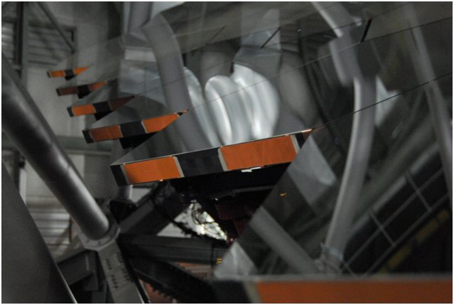
Figure 2. Abandoned capacitive edge sensors mounted to SALT Primary edge sensors
The current sensors make use of mutual inductance between opposing flat coils (a transmitter and a receiver) to measure Piston and Gap. These coils need to work at a nominal fixed separation of 3.5 mm. Since the gaps between segments vary across the array (about 21 mm near the centre to about 8 mm at the edges of the array) the sensors have to be mounted beneath the segments in such a way that a fixed separation can be achieved. Thus, they are bonded to Sitall L-brackets which are clamped to the backs of the segments with a threaded nut and spring arrangement.
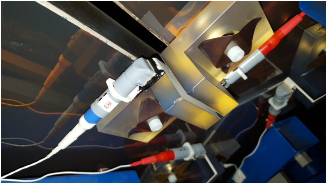
Figure 3. Inductive edge sensor mounted to the underside of a SALT Primary Mirror segment
Signals are carried from the sensors via connectors attached to the sides of the L-brackets. Three sensor pairs on the corners of three contiguous segments are connected by ‘small’ cables to a D-type connector from which a ‘principal’ cable carries the signals to an electronics box in a temperature-controlled igloo. There is a small residual temperature-dependent signal generated in the sensor+cable circuit, but this can be corrected for once temperature coefficients are determined for each receiver-transmitter pair. The coefficients are determined from tests conducted in environmental chambers in Cape Town.
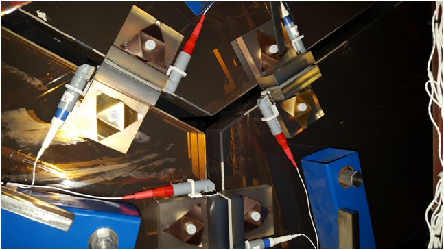
Figure 4. Edge sensors mounted to corner described by 3 adjacent segments
MARS
MARS has the job of converting the Piston signals from the sensors into the actuator displacements required to restore the array to the shape it had at the time of alignment by CCAS. The calculated actuator movements are transmitted to the MACS computer, which acts as a marshal, redirecting the commands to the SPS computer whose job is to actually move the actuators. The signals from the sensors are normally averaged for anything between 10 seconds and several minutes, depending on the rate of change of temperature, to optimize the signal fidelity and reduce the duty-cycle on the actuators.
Tests on the telescope
The first batch of sensors was fitted to the central segment (6 sensor pairs) and to the first ring of 6 segments adjacent to it (3 sensor pairs each) in September 2014, resulting in 24 pairs in total; this is the minimum number that would allow the first ring of segments to be controlled by MARS. Various initial tests verified that all sensors were correctly connected and were producing sensible signals. Subsequently, CCAS is used to compare the alignments of the 7 central segments with those at the time of alignment. This information is distilled into a single number, the ‘rms tip/tilt in arcsec’ (rmsTT).
When specifications were drawn up originally for SALT, a fundamental driver was the image quality (IQ) in the focal plane, as measured by the size of a star image (FWHM). The aim was that the optics should not significantly increase the size of the image above that produced by the typical best seeing (about 1 arcsec). Each optical subsystem – primary mirror, spherical aberration corrector, instrument optics – was allotted a maximum allowed contribution to the image size, ignoring seeing. In the case of the primary mirror, it was 0.439 arcsec, of which SAMS could provide 0.337 arcsec. If all the mirror segments point exactly to the focus, their contribution to image size would be about 0.13 arcsec, the diffraction limit of a 1.0-m mirror (in this case, rmsTT = 0). Since CCAS cannot produce a ‘perfect’ alignment, the image diameter will be larger than the diffraction limit; the best alignment achievable is typically rmsTT=0.05 arcsec. There is a simple relation between FWHM and rms TT, so in terms of the error budget, SAMS is permitted to let rmsTT degrade to 0.11 arcsec. This must pertain over the full operating temperature range of 15 oC, and over a 5 day span during which the central 7 segments are not re-aligned.
Ideally, tests should involve the telescope staring at CCAS, with the latter recording the state of the array as time passes and temperature changes. But this would mean no observing was done. A compromise was reached whereby after approximately 2 hours of observing astronomical targets or when the image quality from the full array had deteriorated, the structure was rotated to point at CCAS, a few measurements were made of the state of the central 7 segments and then science observing resumed. Less than 1 hour of the night over and above the time taken for the usual two to three realignments of the full array was thus spent on monitoring. It was necessary to modify the MACS software so that during a test, when a full alignment was required, the central 7 segments were not moved. The SALT Operators had to learn a new, non-standard procedure, and of course, the weather had to cooperate.
The actuator displacements correct for two effects, one being the supposed uniform change in shape of the truss, the other being any random change due to irregular expansion or contraction or to electronic effects in the sensing circuitry. The first effect is calculated from the mean change in Gap size measured by each sensor; it compensates for a change in Global Radius of Curvature (GRoC) of the array (the apparent focal point moves towards the array as it contracts and the segment have to be pointed outwards to compensate).
Current status
It required one of us to leave South Africa for 7 weeks (of conference and holiday time) to get the whole process to completion. We finally achieved continuous operation for 24 consecutive days after an initial alignment, during which time the temperature in the dome ranged over 20 oC, including one occasion when the temperature decreased at 3 oC/hr (well above the operational requirement of <1.5 oC/hr). This means the system performs to specification, and it is now full steam ahead for the production of the remaining 456 sensor pairs required to populate the full array. These sensors will be constructed in-house and tested for proper operation and temperature sensitivity in our environmental chambers before being installed on the telescope.
Then, slowly but surely, more and more of the segments will be brought under control and the imaging performance of the whole telescope will be gradually improved.