
The Southern African Large Telescope
SALT collects light from astronomical objects and accurately focuses it to one of four focus points. From there the light proceeds into an optical instrument while the telescope tracks the relative movement of the object across the sky to maximise exposure time.
Inside SALT
Select an area of the SALT diagram to learn more!
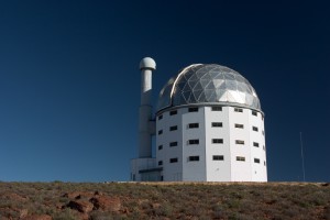
Dome
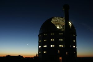
The dome is a 25-meter diameter half-sphere which weighs approximately 30 tons. It rotates to keep the shutter opening aligned with the telescope structure during observations. The dome is thermally insulated to help with controlling the temperature inside the telescope chamber during the day.
Center of Curvature Alignment System
The Centre of Curvature Alignment System (CCAS) is used to align the 91 segments of the Primary Mirror to approximate a perfect monolithic sphere. The system consists of a laser which shines on the Primary Mirror. Reflected light spots are measured by a Shack-Hartman wavefront sensor from which the deviation of a mirror forming a perfect sphere is calculated. The required changes in the tip and tilt of a particular mirror are sent to individual mirror segments.
Dome Shutter
The dome is a 25-meter diameter half-sphere which weighs approximately 30 tons. It rotates to keep the shutter opening aligned with the telescope structure during observations. The dome is thermally insulated to help with controlling the temperature inside the telescope chamber during the day.
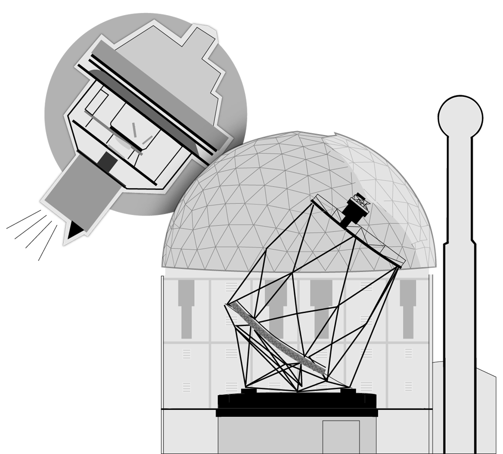
Payload
The payload houses all of the instruments used to analyse light reflecting off of the primary mirror.
Tracker
The function of the tracker is to carry and position the optical payload in the required position and orientation so that the light collected from the primary mirror can enter the Spherical Aberration Corrector and which is ultimately directed to one of the science instruments (*see the payload diagram).
These position and attitude requirements encompass 6 independent degrees of freedom, which is implemented by 10 dependent degrees of freedom. The tracker is supported by the telescope structure at the nominal position of half the radius of curvature of the primary mirror. The telescope structure supports all the interfaces of the tracker to the rest of the telescope system.
The total mass to be supported by the tracker, inclusive of its own weight, is nominally at 4500kg. The mass of the optical payload alone is nominally at 750kg.
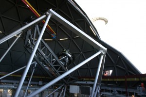
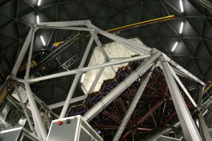
Structure
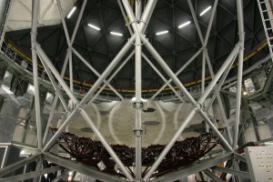
The telescope structure is a very stiff 45 ton tubular steel structure which rests on four feet. SALT’s novel design as a fixed-elevation (53 degrees above horizon) telescope constrain the field of view to an annulus covering 12.5% of the sky at any one time, or 70% of the observable sky. This important design aspect which was taken from the Hobby Eberly Telescope (HET) in Texas, resulted in a significant cost saving in exchange for added complexity of the optical and control systems.
Primary Mirror
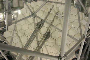
The primary mirror is made up of 91 1m hexagonal mirror segments, each one figured to have a spherical shape. Together these segments make up a 11m in diameter spherical mirror, the largest in the Southern hemisphere. Each segment was manufactured in Russia and is made from Astrositall, a glass-ceramic with a very low thermal expansion coefficient. The mirrors were sent from Russia to Kodak in the USA to be figured. Aluminium is used as the reflective material on the mirror surface which is replaced at least once a year. Each mirror rests on a specially designed mount that allows it to move in tip and tilt using three pistons. This makes it possible for all the segments to be aligned so that they approximate a single monolithic spherical mirror. The mirror segments are supported by a very stiff steel truss that ensures the mirrors stay in place. In the near future edge sensors will be installed on all the mirror segment which will monitor their positions relative to each other. Any change in position for a segment would be detected and corrected, keeping the mirror in shape and ensuring good image quality.
Air Conditioning
Large air conditioning units are used to cool the telescope chamber to the predicted temperatures expected after sunset. Since certain materials in the telescope chamber, like concrete, have a high thermal inertia, these materials would heat up during the day and radiate heat for hours after opening for observing. A heat source in the telescope chamber would cause thermal pockets to rise up, similar to what one can see on a road on a hot day. This is called dome seeing and negatively impacts observations.
Pier
The telescope pier is a concrete ring on which the main structure of the telescope rests. It is the smoothest, flattest piece of concrete ever cast in South Africa, deviating by no more than 1 mm from a flat plane over its ~50 m circumference.
Aluminising Room
The aluminising room is used when mirrors need to be re-coated. Individual segments are removed from the primary mirror of the telescope and moved to the aluminising room where the old coating can be removed. The mirror is then re-coated with aluminium in a vacuum chamber. This re-coating cycle is about two segments a week to ensure that all the segments are re-coated during the course of a year.
Spectrometer Room
The spectrometer room houses the High Resolution Spectrograph (HRS). This room was specially designed with a hole in the ceiling to allow optical fibres to be fed down from the tracker to the HRS.
High Resolution Spectrograph
The University of Canterbury, New Zealand provided the initial design for the High Resolution Spectrograph (HRS). Design revisions and construction began at the University of Durham, UK in 2007, with HRS commissioning following on sky in late September 2013. HRS is the third and final of the first generation instruments for SALT.
HRS specializes in high spectral resolution (the ability to distinguish one wavelength from another) and wavelength stability, in the range 370-890nm.
The instrument is stationary, vibration isolated and housed inside a vacuum tank, and located in a temperature-regulated enclosure in the basement beneath SALT. This keeps the spectrograph insulated against temperature and pressure variations, which would otherwise affect instrument stability. The Fibre Instrument Feed (FIF) couples the four pairs of 50m long optical fibres to the telescope focal plane and allows the selection of the appropriate fibre pair for a given mode, and adjustment of the fibre separation to optimally position the sky fibre.
Key science drivers for HRS include:
- stellar radial velocity measurements (stellar kinematics, extrasolar planets);
- stellar atmosphere analysis (chromospheric activity, seismology, Doppler tomography);
- chemical compositions of stars (abundance analysis, isotopes, nuclear chronometry); and
- interstellar and intergalactic absorption (diffuse interstellar bands, Lyman-alpha forest, high redshift absorbers)
Control Room
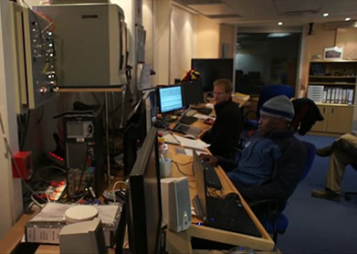
The telescope control room houses all the computers that control the instruments and the telescope. During the day the control room serves as office space for engineers and technicians. At night the control room is dedicated to astronomy operations with a duty astronomer in charge of taking data and an operator who looks after the telescope.
Louvres
The louvres on the sides of the telescope are opened to allow natural airflow through the telescope chamber. This helps to thermally equalise the inside to the outside temperature, and minimizes thermal turbulence inside the dome.
Building
The building walls are thermally insulated and are made from polystyrene sand wedged in between specially made aluminium plates. The building basically acts as a thermos to maintain cold temperatures inside and keep the heat out during the day.
Robert Stobie Spectrograph
The Robert Stobie Spectrograph (RSS) was designed and built for SALT by the University of Wisconsin-Madison and Rutgers University. This instrument is the primary first-light instrument of SALT. RSS will exploit the improved blue/UV throughput of SALT as well as its access to a science field of 8 arcmin diameter. The RSS is capable of normal long slit- and multi-object spectroscopy (MOS) to resolutions of R ~12,000. Additionally, it can perform Fabry-Perot imaging spectroscopy and narrow-band imaging. It was also designed to have polarimetric capability, which has not been commissioned yet.
SALTICAM
SALTICAM was designed to be an acquisition camera as well as a science imager and photometer. It allows the SALT astronomers to identify targets of interest and accurately place these targets either on the RSS slit, the HRS fibre or the BVIT field to be observed. SALTICAM as a science instrument can be used for deep sky imaging. As a photometer, SALTICAM is capable of taking data every few seconds to 20 times a second.
Fold Mirrors
There are two fold mirrors situated in the payload. These mirrors can be inserted into the main light path to divert the light to different instruments in the payload. There is a dedicated fold mirror for SALTICAM and an auxiliary mirror which can be used to either select BVIT or the FIF instrument ports.
Slit Viewer Mirrors
When light is sent through the payload up the RSS for long slit spectroscopy, the target light is sent through a slit on to the spectrograph. The slit is made from a highly reflective metal and mounted at a slight angle to reflect light back down to SALTICAM through a series of mirrors, called the slit view mirrors. One can therefore use SALTICAM to monitor the position of the target object on the slit while making an observation with RSS.
Fibre Instrument Feed
The Fibre Instrument Feed (FIF) in the payload houses optical fibres that feeds light from the tracker down to the HRS in spectrometer room. The FIF allows for very accurate positioning of objects onto an optical fibre. The FIF has its own guide probe which keeps the target object on the fibre during an observation.
Moving Baffle
The moving baffle was designed to keep unwanted stray light from entering the optical path. The moving baffle is a carbon fibre mask in the shape of the primary mirror that moves with tracker to block out any light that does not come from the primary mirror.
Berkeley Visible Image Tube
The Berkeley Visible Image Tube (BVIT) detector is a visible photon counting detector designed to provide observers with very high time-resolution photometric imaging observations of astronomical objects. The instrument is capable of recording photon events with a precision of 25 nanoseconds.
Atmospheric Dispersion Compensator
When light travels through the atmosphere it gets dispersed, much like light dispersed through a glass prism. The amount of dispersion depends on the amount of atmosphere the light travels through. At low altitudes when objects are the closest to the horizon the amount of atmospheric dispersion is at it most. Blue light is dispersed more than red light which results in objects appearing elongated along the vertical. The atmospheric dispersion corrector consists of a pair of prisms which changes their relative distance depending on the altitude of the object to reverse the effect of the atmospheric dispersion.
Spherical Aberration Corrector
The primary mirror consists of 91 spherical mirror segments, this implies that the whole mirror is spherical. Having a spherical primary mirror instead of a conventional parabolic mirror introduces spherical aberration, which causes a degradation of image quality. This can be corrected using the Spherical Aberration Corrector (SAC), a fairly complicated optical arrangement. SALT’s SAC consists of 4 mirrors and sits below the payload to remove the spherical aberration introduced by the primary mirror before the light carries on the instruments.
Calibration System
The calibration system is used to wavelength calibrate spectra and perform flat fielding. The system consists of a optical screen which is inserted below the SAC to inject light up into the payload. A number of arc calibration and flat field lamps are available.
Light from Primary Mirror
Light from the primary mirror enters the payload here.